|
Operational Amplifiers
Operational amplifiers (Op-Amps) were used to solve mathematical equations utilizing analog computers. Based on the configuration, op-amps could add, multiply, integrate, or perform other operations on signals.
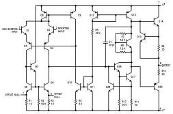 The earliest op-amps were constructed with vacuum tubes. Solid state electronics, of course, allowed circuits to be more compact. Ultimately, circuits such as that shown at right, were developed into integrated circuits. Like most integrated circuits, this greatly simplifies the process of understanding and op-amps.
Common characteristics of op-amps are:
- High voltage gain (80dB or more).
- High input impedance.
- Low output impedance.
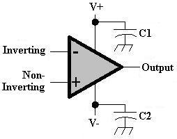 Op-amps have two inputs and one output. In a steady state, the inputs must be balanced because the gain of the op-amp is acting solely on the voltage differential between the two inputs.
The capacitors (C1 and C2) are used to keep the power bus clean and help prevent feedback paths that might cause the op-amp to oscillate. They are often referred to as the bypass capacitors. In order to simplify the diagrams below, the power connections and capacitors are not illustrated.
Symbols and Terms
- Inverting Input: Signals at the inverting input cause the op-amp to respond in the opposite direction. (An increased signal causes the output to decrease.)
- Non-Inverting Input: Signals at the non-inverting input cause the op-amp to respond in the same direction. (An increased signal causes the output to increase.)
- Negative Feedback: Routing of some of the output back to the input in a way to reduce the effect of the input signal, producing a "closed loop".
- Av: Voltage gain.
- Rf: Feedback resitor.
- Vin: The input signal.
- Vi: The inverting input of the op-amp.
- Vout: The output signal.
 Non-Inverting Amplifier
A non-inverting amplifier applies the input signal to the non-inverting input of the op-amp. Two resistors (Rf and R) can form a simple feedback network. Since the input impedance is high, the resitors can be treated as a voltage divider:
Vi = Vout * R / ( R + Rf )
The value of Rf and R can be calculated, once a gain is selected. Using a gain of 2:
- Av = Vout / Vin = ( R + Rf ) / R = 1 + Rf / R -- therefore
- Av = 2 = 1 + Rf / R -- resulting in
- Rf / R = 2 - 1 = 1-- meaning
- Rf = R -- 1 kΩ can be used as a starting point.
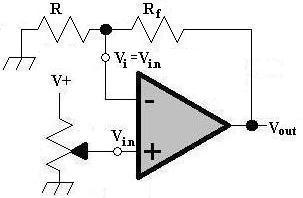
 Inverting Amplifier
Feedback continues to be achieved by the use of resitors Rf and R. The input signal is applied to the inverting input of the op-amp, through R. The non-inverting input is connected to ground. Since the two inputs must be balanced, Vi must also be at ground potential. Since Vi is at ground potential, no current flows into it, meaning:
- Iin = If = Vin / R.
- Vout = - Iin * Rf = - ( Vin / R ) * Rf = - Vin * Rf / R
- Av = Vout / Vin = - ( Vin * Rf / R ) / Vin = - Rf / R
Selecting a gain of -4 and R = 1 kΩ results in:
- Rf = Av * R = 4 * 1 kΩ = 4 kΩ.
 Summing Amplifier
Signals can be combined utilizing an op-amp in a summing configuration. To ensure proper summing, the value of R1 must be equal to R2. Like the inverting amplifier, the non-inverting input is connected to ground. The inverting input is held to ground potential, with zero current into the inverting input. The resulting equations become:
- If = Iin1 + Iin2 = Vin1 / R1 + Vin2 / R2
- Vout = - ( Vin1 / R1 + Vin2 / R2 ) * Rf
- Av = - Rf / R
Based on Hands-On Radio from Apr-2003 QST
| 